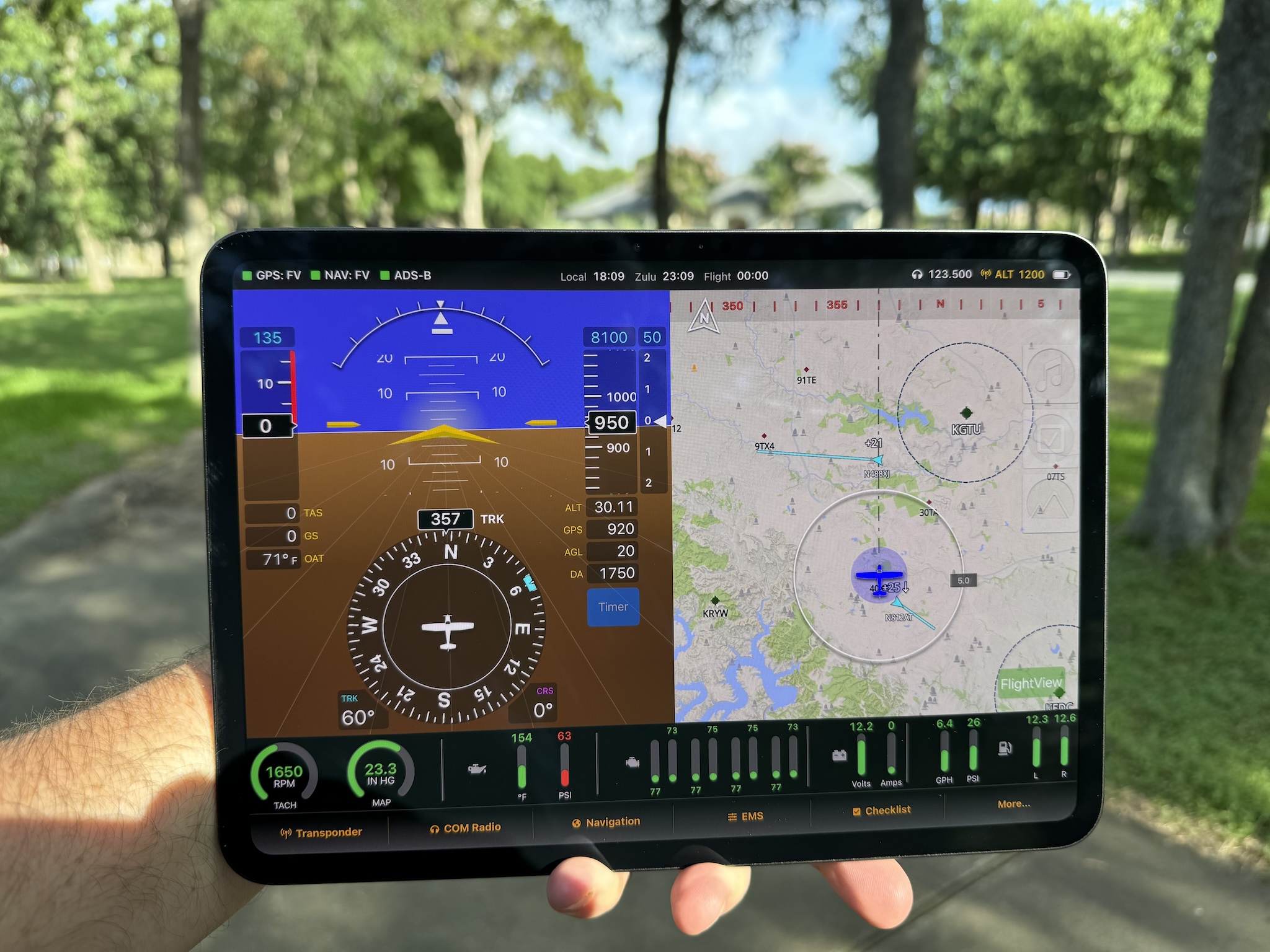
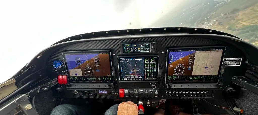
Since launching the FlightView system the majority of the enhancement requests I’ve received are related to the engine monitor. A partial list of these requests includes:
- support for ___ sensor / sender / probe / pickup
- support for liquid cooled engines
- support for engines with speed reduction gearboxes
- support for turbine engines
- support for twin engine aircraft
- support for engines with integrated ECUs (Rotax, ULPower)
- a larger EMS display – half screen, full, screen, both
- user-defined layout of the larger display options
- a vertical EMS bar display
- a flap position indicator
- an elevator trim position indicator
- an aileron trim position indicator
- a landing gear status indicator
- a propeller RPM gauge
- a rotor RPM gauge
- inputs and gauges for additional fuel tanks (auxiliary, tip, header, etc.)
- engine data logging
- support for Savvy Analytics
- on-screen master caution indicator
- output for a master caution indicator
- EGT peak detection
- percentage of rated power calculation
- user-defined gauges
- inputs and indicators for door / canopy / baggage door state
- FWF temperature and / or fire detection
- carbon monoxide detection
All of these are great ideas, and in time I hope to expand FlightView to include all of them. At the moment I’m working on an update that will hit the most popular and important of those.
User Defined Sensors
If you’ve every perused the Aircraft Spruce catalog, you know that there are a huge number of sensor, senders, and probes that can be used to measure and monitor an engine. The initial release supported a very short list of common sensors for traditional aircraft engines. These worked fine for the Lycosaurus on my RV-6A but don’t necessarily work as well for auto conversions or other experimental engines.
The upcoming release will support a wide range of sensors that output their values as a voltage, a resistance, or a sequence of pulses. Most temperature and pressure sensors, fuel tank float sensors, and flap / trim position sensor output either a voltage or resistance. Fuel flow transducers and tachometers often use the pulse technique. This won’t cover every sensor on the market, but it will make FlightView a much more flexible and adaptable product.
Nerdy Details: The EMS analog inputs are capable of reading any sensor that outputs a voltage between 0 and +5 volts. For sensors that are rated by their resistance, we can read values between 0 and 25mΩ. The pulse counter inputs will work with any pulse generator that signals by pulling the line low (below 1v), which covers flow sensors from EI and FloScan and probably others as well.
All custom sensors will require calibration data. In some cases you can get that from the manufacturer. In other cases you will need to perform a manual calibration. I’m adding a calibration utility (similar to the fuel tank level calibration function) which should make the process somewhat easier. For those who are not comfortable plunging sensors into hot oil or hooking them to high pressure lines, I will offer a calibration service at a reasonable price.
New Gauges
I’m adding several new gauges to FlightView. Most of them use the same visual layout as the existing gauges, but two – the flap position Indicator and the trim position Indicator – are new designs. Here’s the full list:
- Auxiliary Fuel Tank 1 – line gauge
- Auxiliary Fuel Tank 2 – line gauge
- Header Fuel Tank – line gauge
- Coolant Temperature – line gauge
- Gearbox Temperature – line gauge
- Turbine Intake Temperature – line gauge
- Carburetor Temperature – line gauge
- Propeller RPM – circle gauge
- Flap Position Indicator – custom indicator
- Elevator Trim Position Indicator – custom indicator
Input Repurposing / Data Source Configuration
In the current configuration there is a fixed linkage between inputs (ports on the EMS box) and gauges. Signals that come in on the “MPR” input are always and only displayed on the “Manifold Pressure” gauge. This is easy to use, but it’s also limiting. The upcoming version will overcome this limitation.
You will be able to select any input as the data source for a gauge. This will let you use the AUX ports. It will also let you repurpose any unused analog ports for something else. Don’t need manifold pressure? You can connect some other sensor to the MPR input, then assign MPR as the source on the appropriate gauge.
Future-Proofing
Making these changes is a major effort. It requires recoding the EMS code in the FlightBox Pro and in the App. While I’m deep in the code I’m revising things to support several of the other major requests: twin engine aircraft, additional general-purpose inputs and outputs, user-defined gauges and annunciators, additional layouts, etc. Once I finish up this project I have several others waiting. When I get back to working on the EMS, the changes I’m making now should make additional enhancements quicker and easier.


